-
1
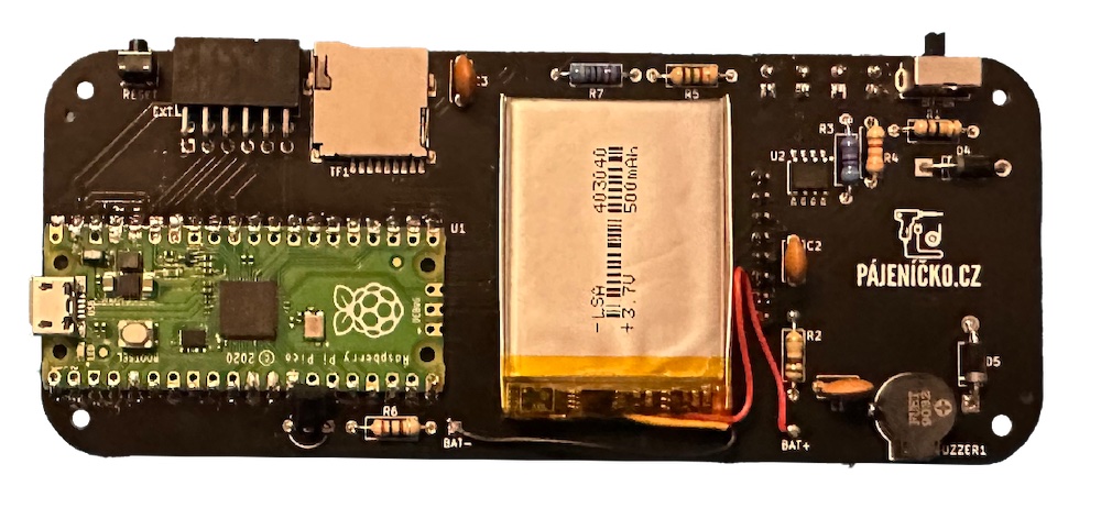
Raspberry Pi Pico
First, solder the Raspberry Pi Pico onto the main circuit board. A TP4056 power supply circuit and a microSD slot are already installed on it from the factory.
-
2
Speaker
Solder the speaker. First, tin one pad on the circuit board, then solder one side of the speaker to this pad. Once it is in the right place, touch the tip of the soldering iron, add a little bit of solder, and solder the second pin.
-
3
Reset button
Solder the small reset button with three pins.
-
4
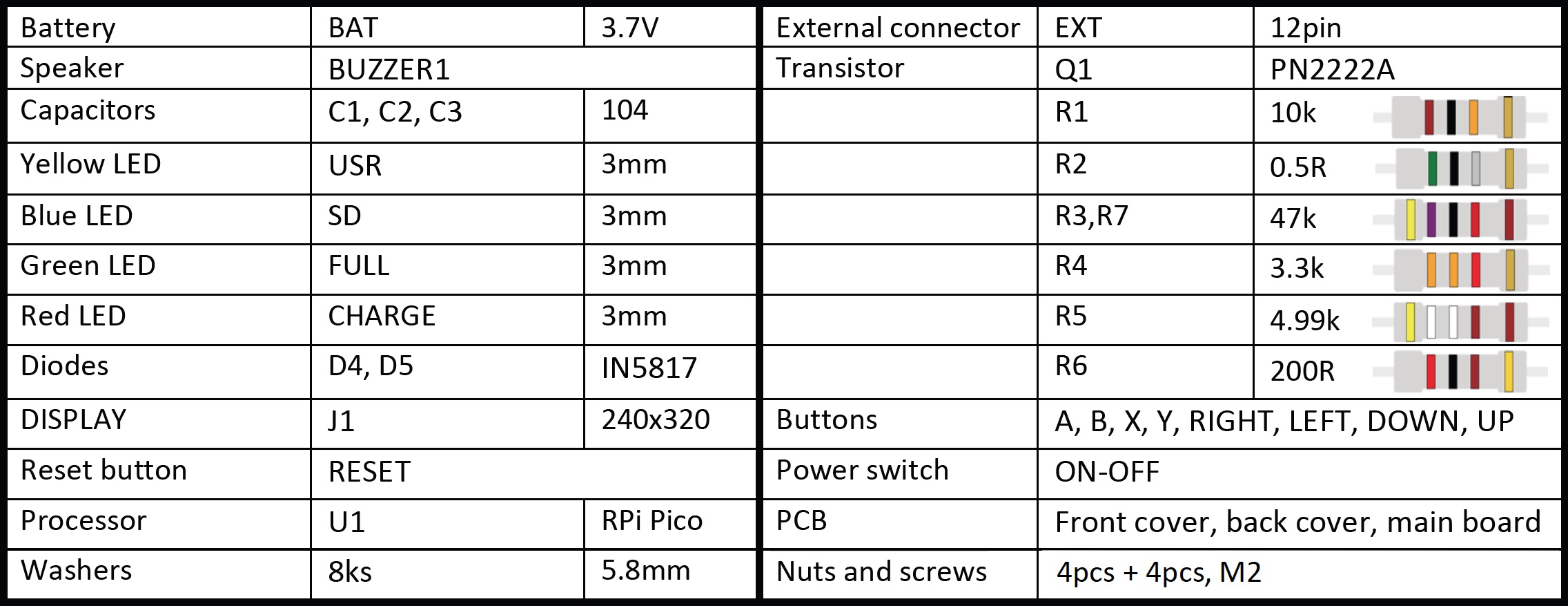
Resistors
Solder resistors R1-R7. You can identify them using a multimeter or by their color coding (see picture at the and of this page).
-
5
Diodes
Solder diodes D4 and D5. Pay attention to their orientation, the white line should be on the same side as it is on the circuit board.
-
6
Capacitors
Connect ceramic capacitors C1, C2, C3 (all have the same value). Gently bend them to the board so they do not stand out and interfere with the rear cover.
-
7
Power switch
The next recommended component is the switch. After soldering, make sure that the switch is in the OFF position!
-
8
Transistor
Install transistor Q1, push it as close as possible to the board and after soldering, bend the transistor towards the Raspberry Pi Pico so it also does not interfere with the rear cover.
-
9
External connector
Next is the external connector with twelve pins.
-
10
Buttons
On the opposite side of the circuit board, solder 8 buttons. I recommend soldering one corner first, it can always be re-heated and the button's position adjusted. When you are satisfied with the position of the button, solder the remaining leads of the button.
-
11
Display
Then solder the display. Remove the protective film on the double-sided adhesive on the back of the display. Make sure you have the display properly aligned. First solder one pin, check that there is no gap between the display connector and the circuit board, ensure the display is straight, and then solder the rest of the pins. There is no need to shorten the connector, it fits into the assembly as a whole.
-
12
LEDs
Next are the LED diodes. Pay attention to the polarity, the longer leg belongs in the round hole. Align the bottom of the diode level with the display circuit board, the diodes are about 2mm from the circuit board. Install the diodes as follows: USR - yellow LED, SD - blue LED, FULL - green LED, CHARGE - red LED. You can align the diodes by temporarily attaching the front cover (see the video for details).
-
13
Battery
Check that the switch is off (on the OFF side). Tin the + and - pads on the circuit board. Carefully take the battery, first solder the negative wire of the battery (black wire to the - pad), then the positive wire of the battery (red wire to the + pad). After soldering the battery, remove the foil from the double-sided adhesive tape on the back of the battery, stick the battery and align the wires so they do not protrude out of the Picopad.
-
14
Screen protector
Carefully remove the protective film from the display.
-
15
Final assembly
Take the front cover and push four screws (M2) through the pre-drilled holes, onto which you put four black washers. Then place the middle (soldered) circuit board on the screws and add another four washers. Next, put on the rear cover, screw on the nuts and tighten everything firmly.
-
16
Testing
And now it's time for fun - turn on the Picopad and enjoy it!
-
Parts list